vPC Overview
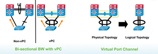
vPC stands for Virtual Port-Channel. This features allows the creation of a cluster of Nexus so that devices connecting to it only see one device. There is no blocked port between vPC and the devices attaching to it and this allow a better usage of the bandwidth.
From a topological point of view, STP does not see two devices but only one. STP sees no loop and therefore no uplinks are blocked. This has the benefit of lowering oversubscription since one more link is effectively working. The load balancing on the Port Channel is performed as usual.
From a licensing point of view, vPC doesn’t require any special licensing.
vPC Terminology
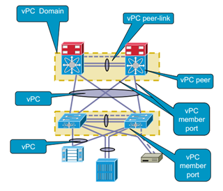
- vPC domain : Two devices that are forming a vPC are in the same vPC domain.
- vPC Peer :Two switches forming a vPC are each others peer.
- vPC Member port : Ports that are inside a Port Chnnel inside vPC and connecting to other devices
- vPC : Designated the combined Port Channel betweel the vPC peers and the downstream device
- vPC peer-link : The link that is used to sync the state between two vPC peer. The peer-link must be 10G
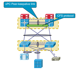
- vPC peer-keepalive : Provide Heartbeat for the vPC peering and act like a backup to the vPC peer-link (Can be routed, Do not use the peer-link to carry it)
- vPC VLAN : VLAN that is carried over the peer-link and used to communicate via vPC with a peer device
- non-vPC VLAN : VLAN that are not carried over the peer-link
- CFS : Stands for Cisco Fabric Services. This is the protocol used for state sync and configuration validation between two peer devices.
Guidelines and Limitations
- vPC can interoperate between different versions of NX-OS during upgrade or downgrade
- vPC peers cannot run different versions of NX-OS outside of the downgrade/upgrade period
- All ports for a given vPC must be in the same VDC
- The configuration of the Peer Keepalive link must be done before the system can form the vPC peer link
- vPC is Layer 2 ONLY
- Each vPC domain must own its own and unique vPC domain ID
- Bidirectionnal PIM or SSM is not supported on vPC
- No DHCP Snooping, DAI or IPSG in vPC. DHCP Relay is supported
- No CFS region is supported
- Port security is not supported on port channels
- Configure a separate Layer 3 Link for routing from vPC peer devices instead of using VLAN network interfaces
- Prefer standard FHRP and PIM timer, aggressive timers give no advantage in vPC
- If OSPF is used in a vPC environment, tune the throttle spf and lsa-arrival timers to ensure fast convergence is a vPC peer link is shut down.
- STP port cost is fixed to 200 in a vPC topology
- A single vPC domain between two VDCs on the same physical Nexus 7000 is no supported
- vPC peer-link MUST be at minimum two 10G interfaces
- Only Port Channels can be in vPCs and it can be a standard Port-Channel or a Fabric Extender Port-Channel
Configuration Parameters
To allow correct vPC operation, some parameters must be the same between two vPC peers. The global recommendation is to configure the Port Channel used to the peer link in trunk mode. When the peer link is configured on both side, CFS messages will provide a copy of the configuration of the local vPC to the remote vPC device, this allows the vPC peers to determine is the condition are satisfactory.
Parameters that MUST be identical
If these parameters are not matching, the vPC will move fully are partially into suspended mode.
- Port-Channel mode : On/Off/Active
- Link Speed per channel
- Duplex mode per channel
- Trunk mode per channel
- Native VLAN
- VLAN Allowed
- Native VLAN tagging : On/Off
- STP Mode
- Region configuration if MST
- Enable/Disable state per VLAN
- STP Global settings
- Bridge Assurance
- Port type
- Loop Guard
- STP Interface settings
- Port Type
- Loop Guard
- Root Guard
- MTU
These parameters can be checked with the command #show vpc consistency-parameters
Parameters that SHOULD be identical
If these parameters are not matching, the result can be a undesirable behavior with the flows
- MAC Aging
- Static MAC Entries
- VLAN Interfaces (Each vPC peer must have the SVI with the same admin and operation mode. VLANs must be created on both device or will be suspended)
- All ACL configuration and parameters
- QoS configuration and parameters
- STP interface settings
- BPDU Filter
- BPDU Guard
- Cost
- Link Type
- Priority
- VLANs
- Port Security
- Cisco TrustSec (CTS)
- DHCP Snooping
- NAC
- IPSG
- IGMP
- HSRP
- PIM
- GLBP
- Routing protocols configuration
vPC mismatch consequences
Prior to NX-OS 5.2(1) if consistency check detects a mismatch on parameter that must be identical, the vPC peer link and the vPC will not come up. If the vPC was already established, the entire vPC is moved into suspended mode and no traffic is allowed across the vPC.
The graceful consistency-check feature has been designed to suspend the link only on the second peer device is a mismatch is detected. This feature is now enabled by default.
vPC outputs
The following #show vpc brief shows the vPC domain ID, Peer Link Status, KeepAlive status, Configuration consistency status, Role and Graceful check feature :
N5K_1# sh vpc brief
Legend:
(*) – local vPC is down, forwarding via vPC peer-link
vPC domain id : 10
Peer status : peer adjacency formed ok
vPC keep-alive status : peer is alive
Configuration consistency status: success
Per-vlan consistency status : success
Type-2 consistency status : success
vPC role : secondary
Number of vPCs configured : 10
Peer Gateway : Disabled
Dual-active excluded VLANs : –
Graceful Consistency Check : Enabled
The next output shows the result of a #show vpc consistency-parameters global.
N5K_1# show vpc consistency-parameters global
Legend:
Type 1 : vPC will be suspended in case of mismatch
Name Type Local Value Peer Value
————- —- ———————- ———————–
QoS 2 ([], [], [], [], [], ([], [], [], [], [],
[]) [])
Network QoS (MTU) 2 (9038, 0, 0, 0, 0, 0) (9038, 0, 0, 0, 0, 0)
Network Qos (Pause) 2 (F, F, F, F, F, F) (F, F, F, F, F, F)
Input Queuing (Bandwidth) 2 (100, 0, 0, 0, 0, 0) (100, 0, 0, 0, 0, 0)
Input Queuing (Absolute 2 (F, F, F, F, F, F) (F, F, F, F, F, F)
Priority)
Output Queuing (Bandwidth) 2 (100, 0, 0, 0, 0, 0) (100, 0, 0, 0, 0, 0)
Output Queuing (Absolute 2 (F, F, F, F, F, F) (F, F, F, F, F, F)
Priority)
STP Mode 1 Rapid-PVST Rapid-PVST
STP Disabled 1 None None
STP MST Region Name 1 “” “”
STP MST Region Revision 1 0 0
STP MST Region Instance to 1
VLAN Mapping
STP Loopguard 1 Disabled Disabled
STP Bridge Assurance 1 Enabled Enabled
STP Port Type, Edge 1 Normal, Disabled, Normal, Disabled,
BPDUFilter, Edge BPDUGuard Disabled Disabled
STP MST Simulate PVST 1 Enabled Enabled
Interface-vlan admin up 2 500 500
Interface-vlan routing 2 1,500 1,500
capability
Allowed VLANs – 1,6-7,10,15,17-18,20-2 1,6-7,10,15,17-18,20-2
Local suspended VLANs – – –
vPC Technical Details and Configuration
Enabling vPC
First, as the NX-OS is a modular software, vPC feature must be enabled with the command (config)#feature vpc. It can be disabled by using the (config)#no feature vpc.
Create the vPC Domain
The vPC domain identifies two peers forming a vPC. Each vPC must have its own and unique vPC domain-ID. Once the vPC domain is created, the peer link linking the two devices will be part of it. The domain-ID is used to automatically create the vPC system MAC address.
vPC domain is created with the (config)#vpc domain ID and this allows to enter the vPC configuration sub-mode.
Configuration of the Peer Keepalive
The peer keepalive must be configured for the system to be able to form the peer link. The peer keepalive is a way for vPC to ensure that the remote peer is reachable much like Hellos in routing protocols. The peer keepalive uses UDP port 3200 to check the reachability.
Layer 3 connectivity is needed between the two peers to configure Peer Keepalive. Best practice recommend to use a separate VRF mapped to a layer 3 interface. Otherwise NX-OS will use the management VRF and management port by default. The peer link should not be used to carry the keepalive. The default timer and configuration ranges are as follow :
- Peer Keepalive Timer
- Default is 1 second, range is 400ms-10s
- Peer Keepalive Hold-Timeout – begins when the peer-link goes down (vPC peer keepalive will be ignored during this time)
- Default is 3 seconds , range is 3s-10s
- Peer Keepalive Timeout – starts at the end of the Hold-Timeout
- Default value is 5 second, range is 3s-20s
The configuration options for the keepalive are available under the vpc domain sub-mode, (config-vpc-domain)#peer-keepalive destination IP
Other options can be used to change the QoS settings of the keepalive. This can be useful if the keepalive needs to go through a routed network to reach its vPC peer, by default the keepalive message has a precedence of 6.
Configuration of the Peer Link
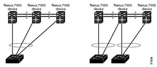
The peer link is the port channel interface used to connect two vPC peers. Cisco recommend using a trunk port and use two ports of different module to enhance redundancy. The peer-link MUST be a port-channel composed of 10G interfaces (at least 1 but 2 recommended) and MUST be point to point. It is used mainly for synchronizing vPC state, consistency parameters and MAC addresses. Only two devices can be vPC peer and one device can only be a vPC peer for one peer. The following diagram shows unsupported topologies :
The configuration is simple as using the keyword (config-if)#vpc peer-link on the port-channel. If needed a list of allowed VLAN can be specified to control which of them are allowed to cross the peer-link.
Once the peer link is defined, consistency checks are made and vPC role election is performed.
4 roles can exists :
- Primary/Secondary : The primary device in the vPC is based on priority and if there is a tie, the lowest MAC address is used
- Operational Primary/Secondary : As there is no preemption with vPC, these roles are met if failover occurs.
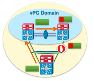
Loop Avoidance with vPC
As STP is not used within vPC, another mean to detect and prevent loop must be found :
- vPC peers can forward all traffic locally
- Peer-link does not typically forward data packets
- Traffic on Peer-link is marked and is not allowed to go egress on a vPC
Traffic that goes across the peer-link is considered as local traffic to the vPC peers.
Nexus 7k specific restrictions
Nexus 7k platform as specific restriction on the peer link as regard to the module used. It is not possible to form a vPC peer link between two different modules
vPC Peer-Gateway
This feature is used to allow the vPC peer that acts as the active L3 gateway to respond to request with the MAC destination of the other peer. Using this feature permit packet forwarding without the need to cross the vPC peer-link. As the peer-link is used to prevent loops in the vPC domain, this feature also prevent potential traffic loss. When this feature is enabled, NX-OS will disable IP redirects message for VLAN mapped to vPC to avoid the sending of ICMP Redirects.
Packets arriving at the peer-gateway device will be TTL decremented. If the TTL is 1 when the packet arrive then drop is to be expected.
Add Port-Channels to vPC
Once the vPC is up, Port-Channels leading to the other devices can be added into the vPC. Typically the devices connecting to vPC are dual attached to the two vPC peers. The same vPC number need to be configured under the Port-Channel leading to a devices.
Once configured, the devices connected to vPC should only see one device though LACP :
Nexus1# sh vpc role
vPC Role status
—————————————————-
vPC role : secondary, operational primary
Dual Active Detection Status : 0
vPC system-mac : 00:23:04:ee:be:32
vPC system-priority : 32667
vPC local system-mac : 00:05:73:eb:1d:41
vPC local role-priority : 8192
Nexus2# sh vpc role
vPC Role status
—————————————————-
vPC role : primary, operational secondary
Dual Active Detection Status : 0
vPC system-mac : 00:23:04:ee:be:32
vPC system-priority : 32667
vPC local system-mac : 00:05:73:e9:fe:c1
vPC local role-priority : 4096
3560_A#sh lacp neighbor
Flags: S – Device is requesting Slow LACPDUs
F – Device is requesting Fast LACPDUs
A – Device is in Active mode P – Device is in Passive mode
Channel group 47 neighbors
Partner’s information:
LACP port Admin Oper Port Port
Port Flags Priority Dev ID Age key Key Number State
Te1/1 SA 32768 0023.04ee.be32 17s 0x0 0x802F 0x4115 0x3D
Te1/2 SA 32768 0023.04ee.be32 9s 0x0 0x802F 0x115 0x3D
Leave a Reply